Welcome to South Africa's Audio Visual community!

Welcome to the home for South African audio and visual equipment owners and enthusiasts. Whether you are an audiophile or a hobbyist, feel welcome to join us in the exciting discussions about amplifiers, turntables, receivers, speakers, projectors, screens, restoration and new projects, product reviews, accessories, classifieds, and so much more!

  • The image upload funtion has been upgraded! Enjoy!

Repair Kenwood KRF-V4080D

Repair and fixing of audio equipment
I spent way too many hours last night trying to find a correct replacement. Sigh ...

Hopefully one will come wondering in today 😉
 
The evening was spent retesting each removed component and then soldering the good functioning ones back in.

I found another problem! IC105 (a BA05T in a TO220FP package) which is a voltage regulator, is suppose to give a steady 5 VDC out as per the specification sheet.

View attachment 5374

If I look at the pins of the BA05T component it shown that pin 1 is on the left hand side:

View attachment 5375


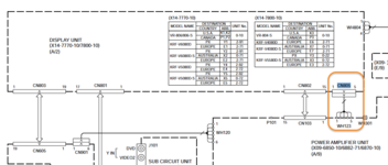
If I look at the circuit diagram for the amplifier it shows that pin 1 is OUT. This is not matching with the specification sheet. See below.


View attachment 5373


If I look at the component diagram and the connections of IC105 to C127 and C125 and C128, then C128 is on the input side and C125 on the output side.

View attachment 5376


Comparing this to the way the IC was installed with the recess to the right hand side, it must mean that leg 1 is connected to C128 and leg 3 connected to C125.

View attachment 5377

This means that the circuit diagram is incorrect and leg 1 and 3 numbering are switched!

I tested the IC as per this diagram and it fails miserably in keeping voltage at 5V.


View attachment 5378


Will replace it as the output voltage and ripple removal function of this IC looks quite important.
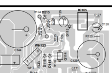
What does this power?

Groetnis
 
Display inoperative I take then, ok not too bad. The input voltage to that VR ok?

Groetnis

The display is not bright so this could be the reason.

I am lost ...

DC rail from WH123.png

IC105 is not installed so I wanted to see if I get the required 6,8V input to it.

If I only apply 230 VAC to pins 3 and 4 on WH119 then I measure 16,7 VAC on the output of transformer T101.

Measuring on the input of D117 ( bridge rectifier diode S1ZB20(4101) ) I get the same 16,7 VAC.

Measuring on the DC side of D117 I get 22 VDC. Nothing else is connected ... I thought maybe my LED workbench lights did some induction, but no. Same when these are off.

Here is a thread as a note to myself that S1ZB20(4101) is not available anymore.
 
I wonder who turned this amplifier into this massive puzzle.

Had a look at the mini PS circuit in the post above tonight.

C132 is broken, resistor R123 is open, diodes D114 and D115 measures OK, but touching the one makes the forwarding voltage vary. Sug ... genade tog!

I still get the 16V out of the transformer T101 and about 21 VDC out of D117. This with C132 and R123 removed. Check the LED lighs. They induce about 2V which the capacitor C129 sucks in and stores. But it still does not add up to the 21V.

Maybe I discovered an energy gain device!!

EDIT: Seems like it can actually do gaining with no load. Interesting article!

D114 and D115 are 1SS133 which is unobtainium. Will a BAS45A be a suitable replacement?

EDIT: The BAS45A is a medium switching diode. A 1N4448 is the correct replacement.
 
Amazing how the human brain works when given time ....

I measured 16,7V on the output transformer T101. Today while working, the 6,7 popped up in my brain and the word typo!

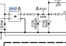
I went back to the PCB this afternoon, switched off the LEDs and measured again. +16.8V the DMM showed ... Yes, someone made a typo and missed the "1" below.

1713535842692.png

I check the specification sheets for the D117 which can handle 200V AC and the IC105 (BA05T) can handle 25VDC so all is good! These voltage values both are more than the 16,8V supplied by T101. This confirms to me that the circuit was designed for a supply voltage lower than 25VDC and therefor my logical deduction is that it must be a typo in the circuit diagram.

The puzzle of this repair is quite a serious one. Feels like someone threw the lid of the box away!
 
Zener diodes D307, D311, D312, D314 and D316 are all MTZJ3.9(B) diodes with a 3% voltage variation as can be seen in the extract from the specification sheet

1713551745039.png

The replacement I can find is a TZX3V9C-TR. Only issue is I need to buy a minimum quantity of 200. Maybe someone has 5 that they can gift?

Interesting I see Mouser now ship for free to SA when the order is more than R2000. Dunno when this changed as Mouser was always too expensive due to the shipping fees they charged. Let me see if I can order small quantities from Mouser!
 
Last edited:
#crosseyed ... #PCBdryjointsresoldering ...

Finished resoldering the other two PCBs. The input board had so many dry joints that I gave up counting. Was once again close to or more than 50%.

The microprocessor board has one voltage regulator with two dry joints. Reminder to myself - check if this and the bridge rectifier is still OK.

IMG_2541 copy.png

IMG_2542 copy 2.png
 
My explanation above about the voltage driver for the STK chips was wrong.

It seems the STK chip gets +/-43.3V max on pins 12&13.

D305[10V]+D306[10V]+D319[11V]+D320[13V]-1*Vbe[0.7V]

It never gets +/-76V. The output stage does indeed switch between +/-46V and +/-76V (done independently by comparators inside the STK chip.) So the Output stage gets a lot more voltage than the stages driving it. Presumably this is done to account for significant voltage ripple on those +/-76V lines when driving many loads (in surround mode.)

So I'm thinking pin 12&13 see around +/-19.3 Volt during normal operation, when Q405 is on, and they get +/-43.3V via Q403/406 when a higher signal voltage requires it, as determined by the microprocessor (IC804 pin 74 controlling Q405).

This explains a couple of other things. +/-43.3V supplies on pin 12&13 should enable the output stage to deliver the specced ~100W in 6 Ohms. If the voltage amplifier bits could swing the STK chip's output stage to +/-76V the spec would have been closer to 400W per channel, and the amp would weigh a ton.

I'm slightly less worried about Q406 now. I can see it surviving switch-on without excessive C-E voltage and if Q402 switches on, effectively grounding the bases of Q406 & Q403, R996 should keep it alive.

About measuring the diodes, if you touch them they heat up to your body temperature, causing the forward voltage to drop. Same with transistors of course.

I've not come across dodgy diodes much. They always seem to fail with gusto, either open or short circuit. So either I've been very lucky, or I haven't been paying attention... I imagine applying max reverse voltage and checking for leakage (checking voltage drop across a resistor in series with the diode) is the failsafe check, One would need a pretty high supply voltage to do this for many of the common audio diodes. Not being a valve guy I'm nervous of having a kilovolt+ on the bench for those 1N4007s.

About the dry joints, I'm led to believe that all Lead-free joints look like dry joints. Never went Lead-free myself. While the principle seems nice enough I'm not convinced that the Lead-free move in the industry was a smart one. I got the explanation upstream wrong because of natural stupidity, not Lead poisoning. Now the obvious question is can one trust my opinion?
 
A quick update. I have compiled my list of components on RS and Mouser and the latter works out a lot cheaper due to the fact that I do not need to order minimum quantities.

In fact the total amount is too low to qualify for free shipping. This means I am compiling a new list of components for the Quad 303 project which will allow me to increase my order total to get that free shipping!

Is anything ever free in life ... ??
 
My explanation above about the voltage driver for the STK chips was wrong.

It seems the STK chip gets +/-43.3V max on pins 12&13.

D305[10V]+D306[10V]+D319[11V]+D320[13V]-1*Vbe[0.7V]

It never gets +/-76V. The output stage does indeed switch between +/-46V and +/-76V (done independently by comparators inside the STK chip.) So the Output stage gets a lot more voltage than the stages driving it. Presumably this is done to account for significant voltage ripple on those +/-76V lines when driving many loads (in surround mode.)

So I'm thinking pin 12&13 see around +/-19.3 Volt during normal operation, when Q405 is on, and they get +/-43.3V via Q403/406 when a higher signal voltage requires it, as determined by the microprocessor (IC804 pin 74 controlling Q405).

This explains a couple of other things. +/-43.3V supplies on pin 12&13 should enable the output stage to deliver the specced ~100W in 6 Ohms. If the voltage amplifier bits could swing the STK chip's output stage to +/-76V the spec would have been closer to 400W per channel, and the amp would weigh a ton.

I'm slightly less worried about Q406 now. I can see it surviving switch-on without excessive C-E voltage and if Q402 switches on, effectively grounding the bases of Q406 & Q403, R996 should keep it alive.

About measuring the diodes, if you touch them they heat up to your body temperature, causing the forward voltage to drop. Same with transistors of course.

I've not come across dodgy diodes much. They always seem to fail with gusto, either open or short circuit. So either I've been very lucky, or I haven't been paying attention... I imagine applying max reverse voltage and checking for leakage (checking voltage drop across a resistor in series with the diode) is the failsafe check, One would need a pretty high supply voltage to do this for many of the common audio diodes. Not being a valve guy I'm nervous of having a kilovolt+ on the bench for those 1N4007s.

About the dry joints, I'm led to believe that all Lead-free joints look like dry joints. Never went Lead-free myself. While the principle seems nice enough I'm not convinced that the Lead-free move in the industry was a smart one. I got the explanation upstream wrong because of natural stupidity, not Lead poisoning. Now the obvious question is can one trust my opinion?
Thanks so much for this detailed explanation! Makes my searching quest so much easier and teaches me some more!

Dry joints. I tried resoldering with lead free solder and it and the existing pad solder did not want to work. Switching to lead containing, it works a charm. So, who knows what was used on these Kenwood PCBs wayback in 2006? Interesting read is the extraction from a Kenwood Bulletin (note the dates).


1714542100919.png
 
Send me the list. I'm in Pretoria but I might have some of the required parts, then you can see what the most economical option is.

Also maybe consider a quote from TRX www.trxe.com if you already have the Mouser part numbers. They're one of the companies representing Mouser here. I never saw a shipping charge on their invoices. I'm guessing they have very regular large shipments. They've been very helpful to me with things that are difficult to find locally.
 
@ludo has been so kind to assist me with the process of obtaining components in SA. Once we have finalised the list I will post of our sleuthing achievements!
 
A quick update. Between @ludo and myself (with me making the mistakes as a learner), we managed to figure out the components that are physically able to fit and will also electronically work correctly.

Currently I am waiting on some of these parts to arrive with a Mouser order @ludo placed.

Thanks again for all your patience and kind assistance @ludo !
 
Back
Top